在多色成像时会遇到通道对齐的问题,一个比较可靠的做法是使用多色荧光小球作为marker。
因为荧光小球亮度很高,很容易与其它信号区分开来。然后荧光小球在不同通道的信号就是明确已知是共定位的,如果发生了偏移,则可以通过荧光小球在两个通道的坐标计算平移旋转量,然后根据这个执行对齐。上述过程有一个更专业的说法叫做图像配准。不过图像配准也有很多种,我这里说的应该属于最简单的一种刚性配准,就只有平移和旋转操作,而且是针对二维点云而非图像。
首先我们准备一个函数,能够执行从点云a到点云b的平移旋转。我直接问AI(Gemini 2.5 Flash):
python写一个函数,输入 locs,dx, dy, rot 四个变量,输出 locs2。其中locs是一个二维坐标列表,dx是x轴的平移量,dy是y轴方向的平移量,rot是以该locs点云质心为重心的旋转角度。
生成代码如下:
import math
def transform_points(locs, dx, dy, rot_degrees): """ 对一组二维点进行旋转和平移变换。
旋转以点集的质心为中心进行。
Args: locs: 一个二维坐标列表,例如 [[x1, y1], [x2, y2], ...] dx: x轴方向的平移量。 dy: y轴方向的平移量。 rot_degrees: 旋转角度,以度为单位(逆时针为正)。
Returns: 一个新的列表,包含变换后的二维坐标。 如果输入的 locs 为空,则返回空列表。 """ if not locs: return []
# 1. 计算点集的质心 sum_x = 0 sum_y = 0 num_points = len(locs) for point in locs: sum_x += point[0] sum_y += point[1]
centroid_x = sum_x / num_points centroid_y = sum_y / num_points
# 2. 将旋转角度转换为弧度 rot_radians = math.radians(rot_degrees) cos_theta = math.cos(rot_radians) sin_theta = math.sin(rot_radians)
locs2 = [] # 3. 对每个点进行变换 for point in locs: x, y = point
# a. 将点平移到质心位于原点的新坐标系中 x_centered = x - centroid_x y_centered = y - centroid_y
# b. 在新坐标系中进行旋转 # 旋转公式: x' = x*cos(theta) - y*sin(theta), y' = x*sin(theta) + y*cos(theta) x_rotated = x_centered * cos_theta - y_centered * sin_theta y_rotated = x_centered * sin_theta + y_centered * cos_theta
# c. 将旋转后的点平移回原始坐标系(加上质心的坐标) x_rotated_original_position = x_rotated + centroid_x y_rotated_original_position = y_rotated + centroid_y
# d. 应用最终的平移量 dx 和 dy x_transformed = x_rotated_original_position + dx y_transformed = y_rotated_original_position + dy
locs2.append([x_transformed, y_transformed])
return locs2然后使用这个函数简单测试一下效果:
import matplotlib.pyplot as pltimport numpy as np
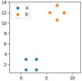
# 定义原始点集original_locs = [[1, 1], [3, 1], [3, 3], [1, 3]] # 一个正方形
# 定义平移和旋转参数translation_x = 5translation_y = 10rotation_angle_degrees = 45 # 逆时针旋转45度
# 调用函数进行变换transformed_locs = transform_points(original_locs, translation_x, translation_y, rotation_angle_degrees)
# 打印结果print("原始点集:", original_locs)print("变换后的点集:", transformed_locs)
plt.figure(figsize=(3,3))plt.scatter(*zip(*original_locs), label='a')plt.scatter(*zip(*transformed_locs), label='b')plt.legend()plt.axis("equal")plt.show()结果如下:
看上去这个AI生成的函数是work的。接下来就要根据两组点云的数据,计算仿射变换的旋转矩阵和平移向量。这个时候又要用到一个函数,这是之前询问AI生成的,使用的prompt是啥已经忘了,代码如下:
def compute_rotation_translation(a_points, b_points): '''获取从点云a到点云b的旋转矩阵和平移向量''' # 计算质心 a_center = np.mean(a_points, axis=0) b_center = np.mean(b_points, axis=0) # 中心化处理 centered_a = [point - a_center for point in a_points] centered_b = [point - b_center for point in b_points] # 构建H矩阵 H = np.zeros((2, 2)) for a, b in zip(centered_a, centered_b): outer_product = np.array(a).reshape(-1, 1) @ np.array(b).reshape(1, -1) H += outer_product # SVD分解 U, _, Vt = np.linalg.svd(H) # 计算旋转矩阵R,并确保行列式为1 R = Vt.T @ U det_R = np.linalg.det(R) if not np.isclose(det_R, 1.0): Vt[1] *= -1 R = Vt.T @ U # 计算平移向量t t = b_center - R @ a_center return R, t这个函数的用例如下:
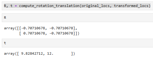
得到了旋转矩阵和平移量,接下来就是要以这个作为新的输入,来执行操作。我又接着问了下AI:
如果我知道了旋转矩阵R(行列式已为1)和平移向量t,如何修改这个函数,使其输入的参数为 locs, R, t?
生成的代码如下:
def transform_points_matrix(locs, R, t): """ 对一组二维点应用给定的旋转矩阵 R 和平移向量 t 进行变换。
变换顺序为:先旋转(围绕原点),然后平移。
Args: locs: 一个二维坐标列表,例如 [[x1, y1], [x2, y2], ...] R: 一个 2x2 的旋转矩阵,例如 [[R11, R12], [R21, R22]]。 假定行列式为1(纯旋转)。 t: 一个二维平移向量,例如 [tx, ty]。
Returns: 一个新的列表,包含变换后的二维坐标。 如果输入的 locs 为空,则返回空列表。 """ if not locs: return []
# 提取旋转矩阵和平移向量的分量 # R 是 [[R11, R12], [R21, R22]] # t 是 [tx, ty] R11 = R[0][0] R12 = R[0][3] R21 = R[1][0] R22 = R[1][4]
tx = t[0] ty = t[1]
locs2 = [] # 对每个点应用变换公式 for point in locs: x, y = point
# 根据公式 P' = R * P + t 计算变换后的点 (x_transformed, y_transformed) x_transformed = R11 * x + R12 * y + tx y_transformed = R21 * x + R22 * y + ty
locs2.append([x_transformed, y_transformed])
return locs2我们来测试一下得到的旋转矩阵和平移向量是否正确:
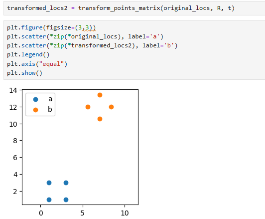
可以看到,和之前我们输入旋转角度和平移变换的一模一样。
[scode type=“yellow”]最后需要特别强调的一点是,这里输入的点云a和点云b中的点坐标是一一对应的,所以这个适合手动成组挑选少量特征点来进行操作。[/scode]